Like many of you nerds, a nerd like me when I was a little kid, I enjoyed tearing down stuff, putting it back together, and ensuring it worked. Somehow, I naturally desire to understand how things work and build stuff. One of my favorite books is The Way Things Work:
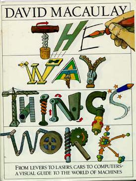
The Way Things Work book cover image
Highly recommended, by the way.
Just tearing down things and putting them back cannot contain my desire to build stuff at some point, so I became obsessed with programming. Over the decades, I felt very comfortable building things in the virtual world, but it’s becoming too comfortable. For now, I have the confidence to build almost any large-scale complex software system from the ground up by myself or with a team. Nevertheless, I still want to build something I can touch in the real world.
However, building things in the real world is challenging because the real world is messy, unlike the virtual world, which is usually binary. Although I don’t hate handcrafting stuff, there needs to be a significant improvement in the translation from idea to reality. Time consumption is also an essential factor. That all changed after 3D printers became more and more popular. You can print things as you designed. However, the problem with 3D printers is that I have heard that there are so many problems when you try to print something with it. I don’t want to spend most of my time troubleshooting printing problems; I want something that just works and focuses on design and iterations.
As you can see from my previous article, I built a mini-PC-based bare metal Kubernetes cluster with USB4 as the high-speed networking interface. Since then, the cluster has been sitting on the corner of the floor in my office, and it organically extended with different devices and got a bit messy over time. Cooling is also a concern because the three nodes stack together. There needs to be more room for good ventilation.
To improve the situation for my cluster, I had the idea of using a 3D printer to build my modular mini server rack. A while back, I realized that the 3D printers community recommends printers from Bambu Lab a lot. Most of them claimed it’s finally out-of-box and print. Then I wondered
Okay, maybe it’s the time. Let me build this! 🤔
However, since the money-saving spirit is hardwired in my DNA, I’m always jealous of YouTubers who get free stuff to review. Old school dinosaurs like me, who only write articles instead of making fancy videos, wondered why not ask them for sponsorship of my mini PC server rack project. So I asked. And YES, today I am happy to announce that this article is sponsored by … um…. nobody but myself once again!
So yeah, no, they didn’t reply 😂
Okay, fine. Who am I to ask for a sponsorship from? Since then, I have buried the idea deep down in my mind until recently, when I saw there’s a black Friday discount. Given that they aren’t sponsoring my tiny project, I have no choice but to punish them with money. So I did. Sorry, just being salty.
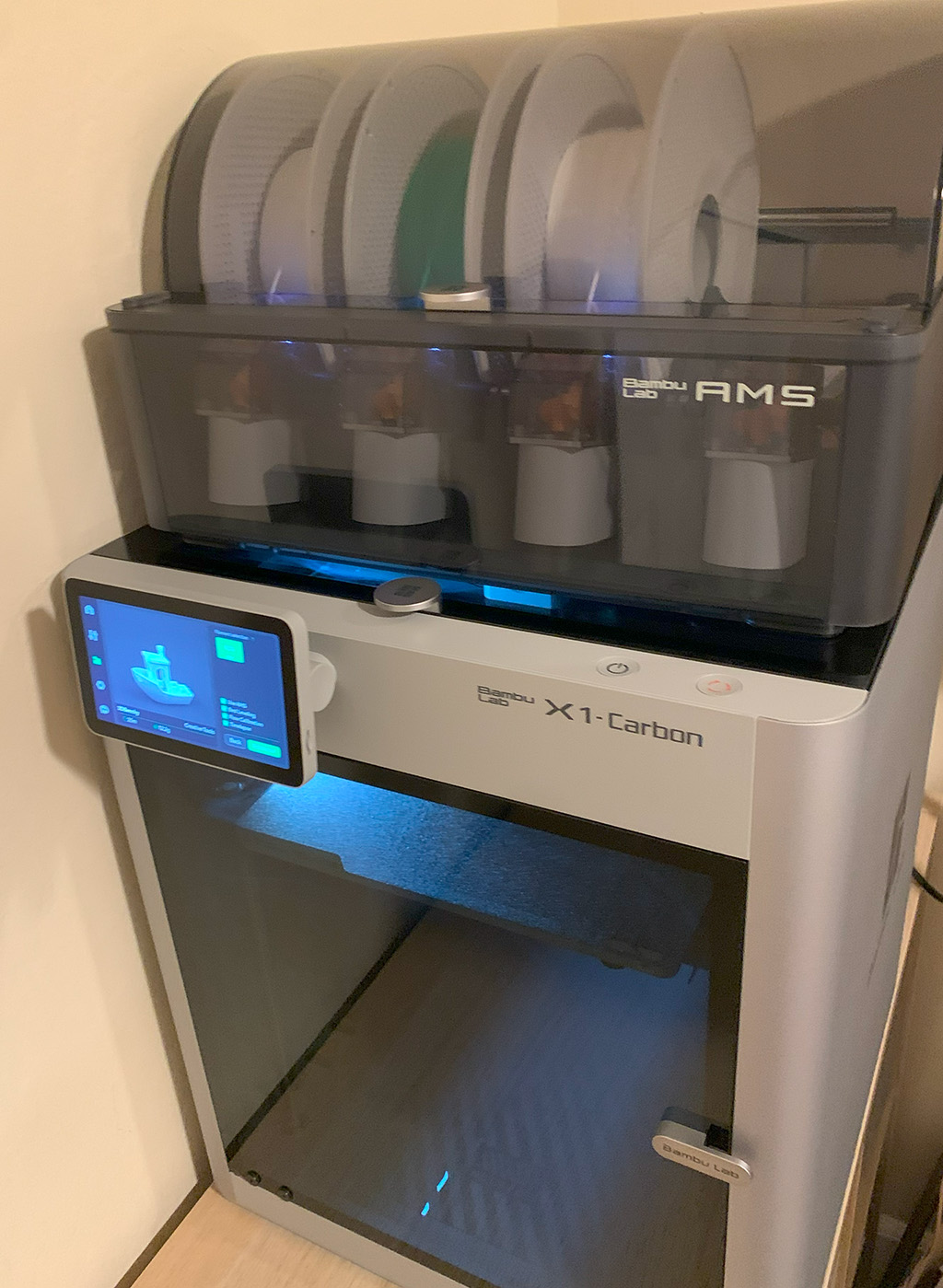
Since then, I have printed some little stuff and learned a little about CAD (Computer-aided Design). Surprisingly, my software engineer experience could translate into CAD. Today, I would like to share my experience of playing with 3D printers and also learning CAD from a software engineer’s perspective. This would be a series of articles sharing my experience moving toward the goal of building my cluster’s modular server rack. Hope you will like it, and here we go!
Printing is easy with Bambu, as most people claimed
Without any prior 3D printing experience, I could unbox the printer, install it in 30 minutes, and print the famous benchy immediately without almost any learning curve by simply following the instruction.
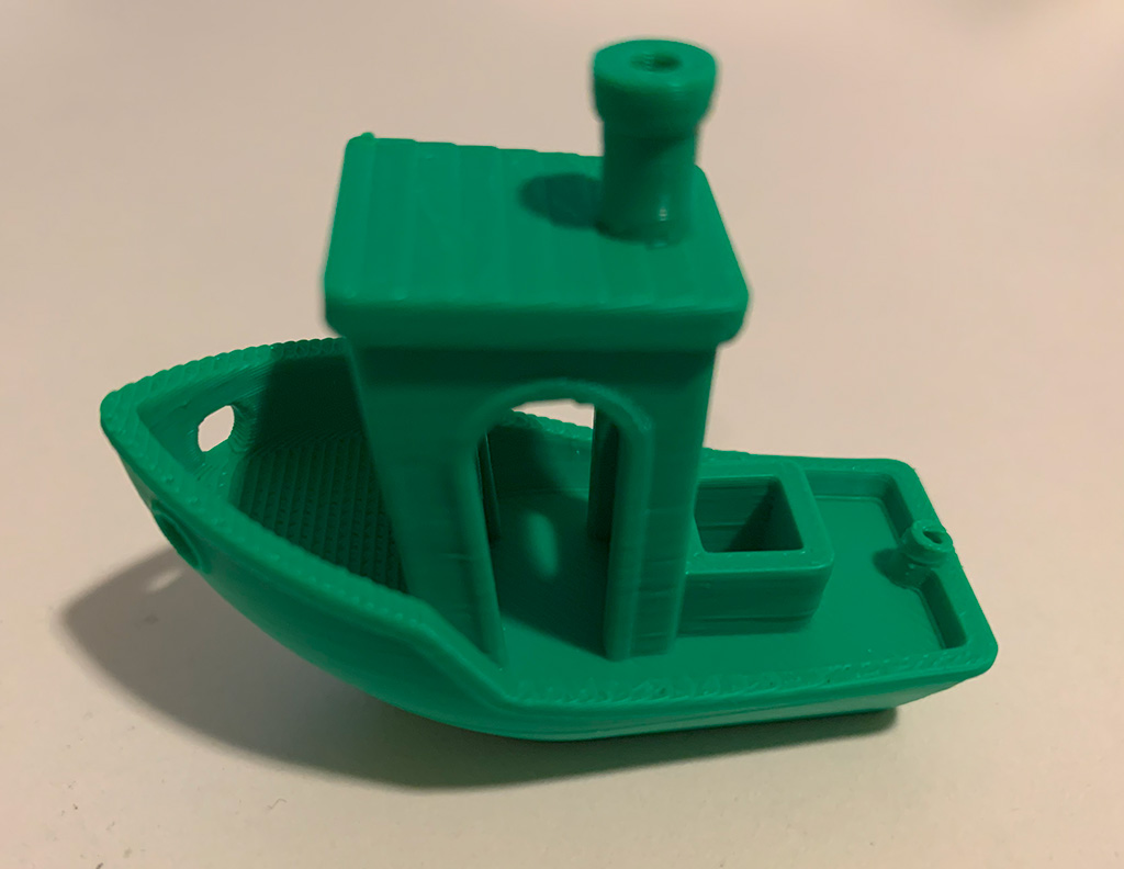
3D printed benchy
People say that it is a 3D printer as if Apple had made it, and I agree. It just works. To clarify, I have watched many 3D printer videos before but never really operated one. Then, I printed a dual-color benchy to ensure the AMS (Automatic Material System) worked as expected. And once again, it just works.
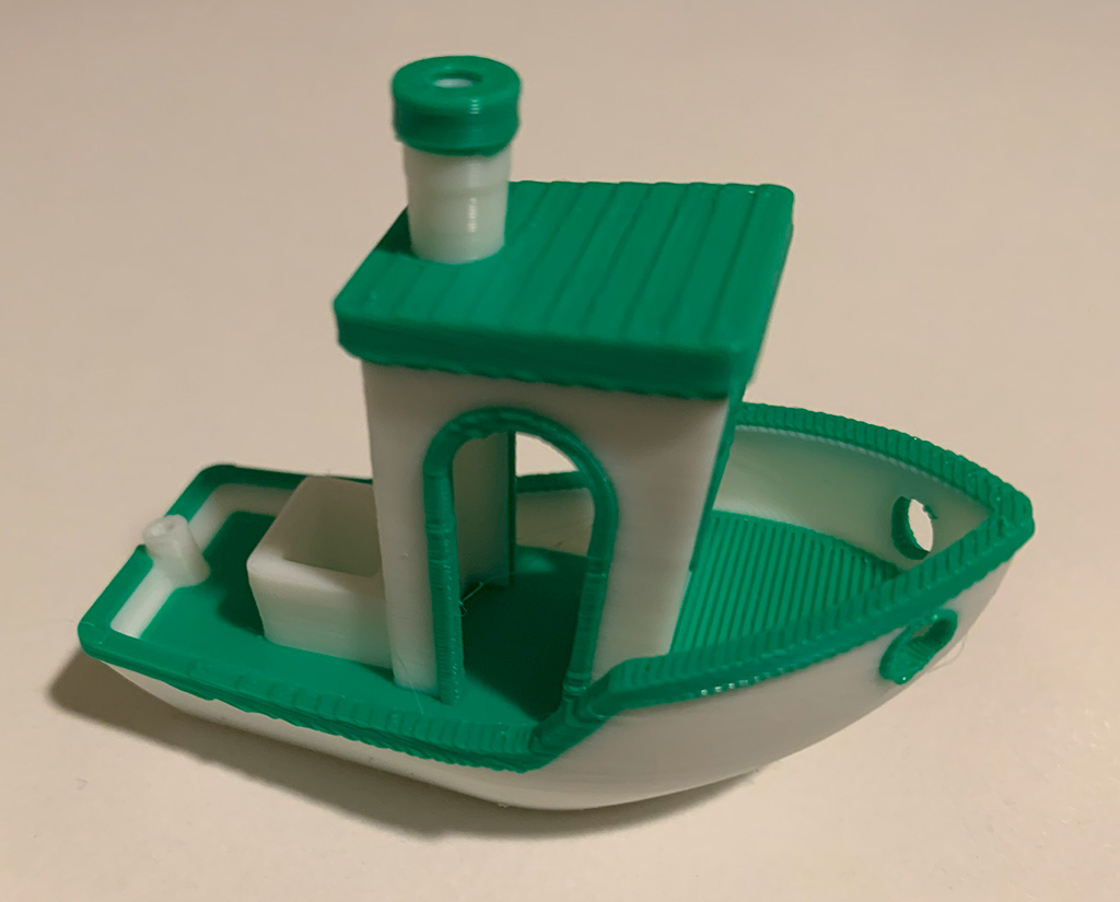
3D printed dual color benchy
I heard that multi-color print consumes a ton of material plus takes a super long time, and indeed, it did! The printer created a purge tower for cleaning and stabilizing the flow before printing the actual object, and it made many poops for swapping out the current printing color.
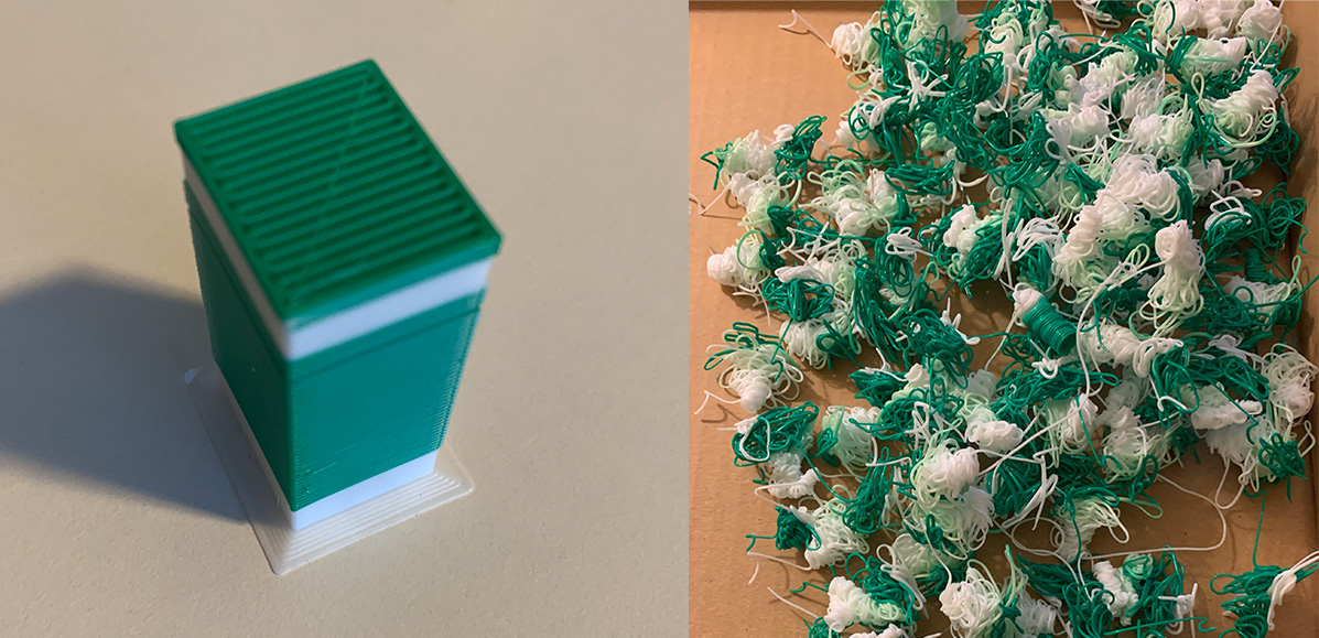
3D printing purge tower and poop
It’s too wasteful and slow for my taste, so I will only print with multi-materials if necessary. Or, maybe I will break them down into different components and then assemble them in most cases.
Each Bambu Lab printer comes with a tiny printing project in it. The one I got is this lamp, and I printed it. I have to say, it’s gorgeous.
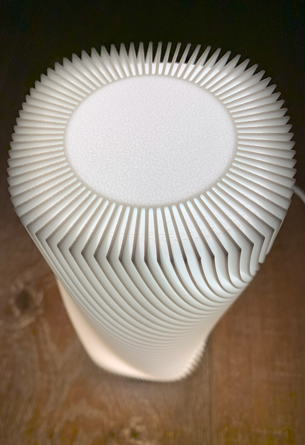
3D printed Bambu Lab's LED lamp
I don’t have enough time to get the white balance right but trust me; this looks way more beautiful when you see it in person. 😍
I am very interested in mechanisms, particularly the Compliant Mechanism. It’s cool that you can have a tool that works with minimal or no assembly and works right out of the printer. Therefore, finally, I printed this:
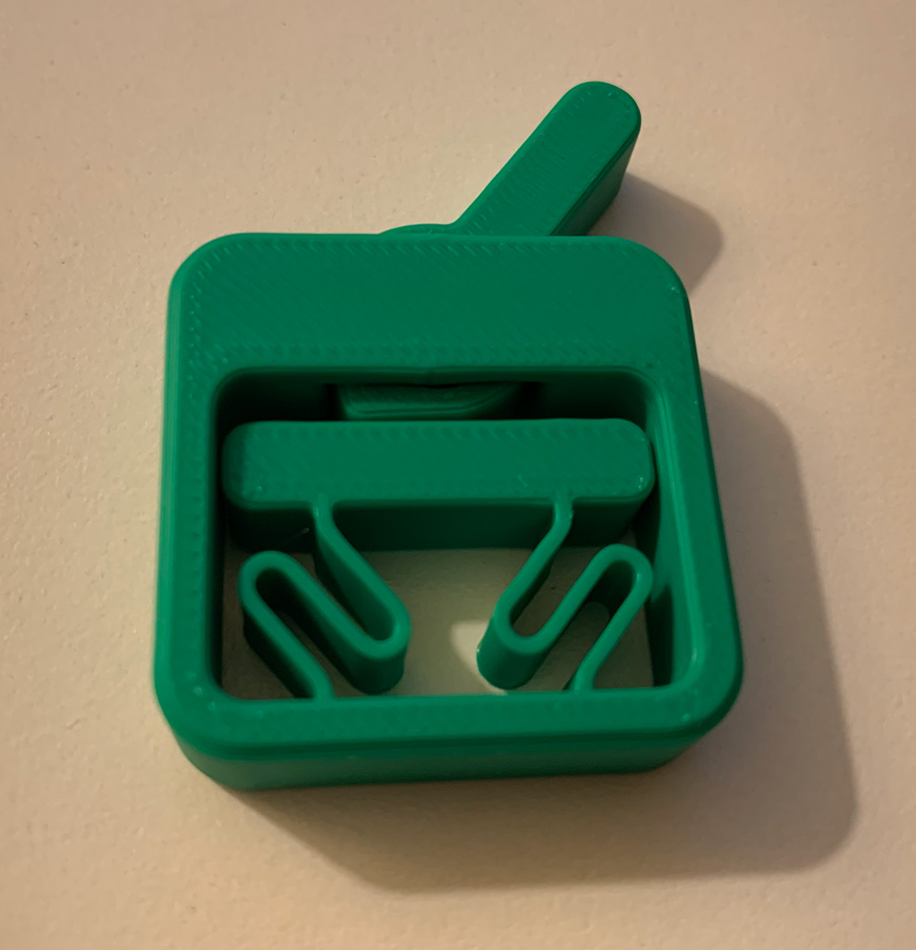
3D printed fidget toggle switch
As expected, this little gadget works coming out of the printer. The Compliant Mechanism is another awesome topic; if you’re interested, you can watch this series of videos to learn more about it.
It’s the CAD time!
Enough of printing. So far, I have confidence that this printer will work as expected, and the only limit left is my imagination and knowledge. Learning CAD is the next step. I did some quick research and realized there are countless CAD programs available. I don’t want to spend too much time researching which one to use, so I stick with the most popular one, Fusion 360. Besides its popularity, the free license for personal projects is also beneficial, as I want to wait to buy it until I am ready to use it for my major project.
Now, I have decided to use Fusion 360. The only problem is – what to build first. Certainly, my final goal is to create a modular server rack for my cluster, but the gap in experience is too significant to jump from a totally newbie. As I mentioned in my other article about how I learn programming by building MMORPG or my book, I usually detour with smaller pioneering projects to gain the needed experience and confidence in a tool or technology before jumping into a bigger complex project. Similarly, designing a decent modular rack system takes a lot of work. Indeed, it’s better to start smaller.
When I was thinking, I looked up from my screen and found a perfect project for it:
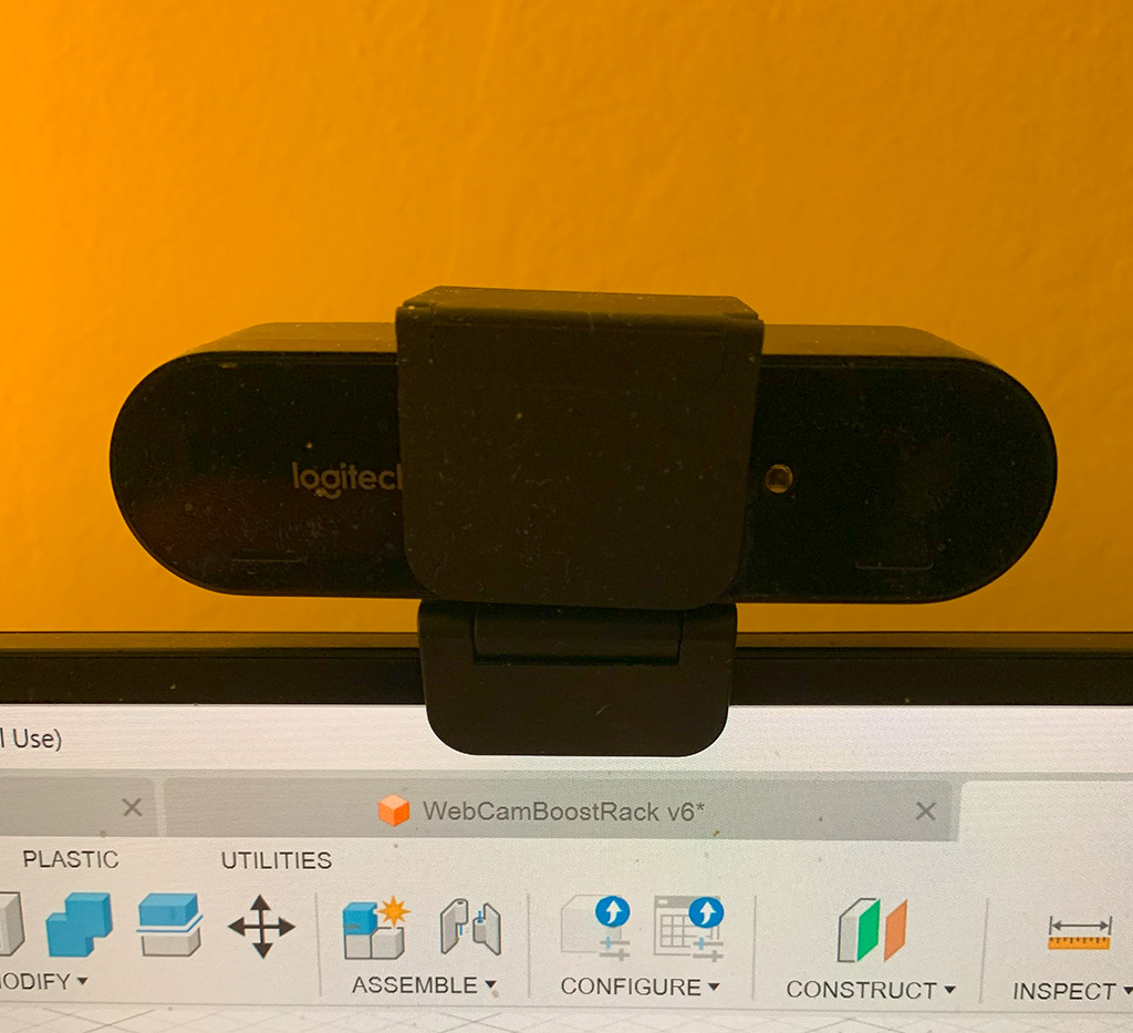
Webcam mount blocks the top edge of my screen
This webcam mounts on top of my monitor. But its mount’s front-facing part dips too much down beyond the bezel, and it ends up blocking my screen. How did I solve it? LowTechButItWorks™️:
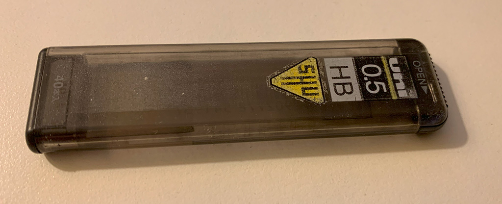
The case of Uni Pencil Lead
I recall thinking about finding a better solution to this problem. That once again proves that once a solution works without an obvious problem, it becomes immortal and stays forever 😅
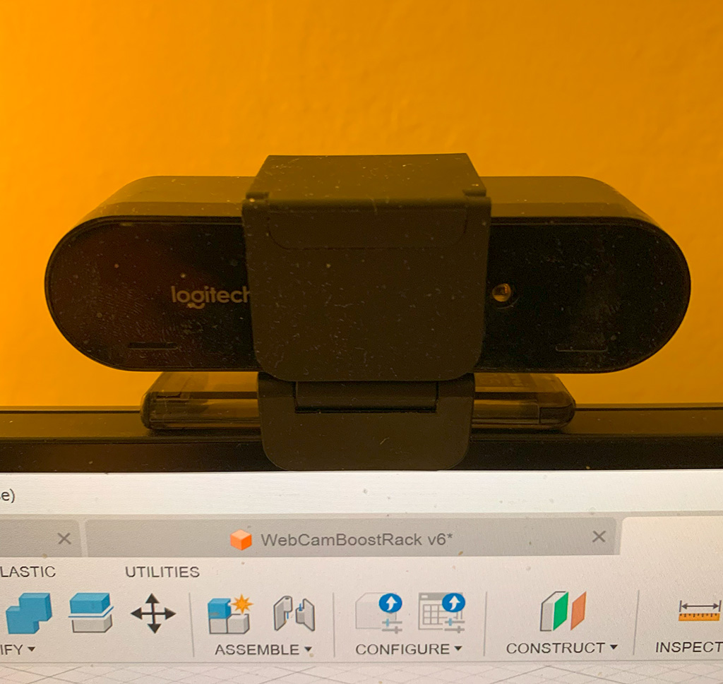
Webcam mount riased by the pencil lead so that it's not blocking the top edge of my screen
I understand the idea of don’t fix something that is not broken. Also, using CAD to design and build a custom raiser with a 3D printer is a bit overengineering from a practical engineering perspective. However, since I am learning something new, deliberate practice is very critical. So I just did anyway. I watched this series of Fusion 360 tutorial videos and picked it up very soon because I could translate my prior programming experience to CAD design.
CAD sketch constraints are similar to iOS UI constraints
As a software engineer, at some point, I mainly worked on iOS apps for a startup. And if you happen to build UI with iOS, then you know you can define UI with constraints. In CAD, to build a model, you will usually draw a sketch on a 2D surface and then use extruding or other operations to expand it into a 3D model.
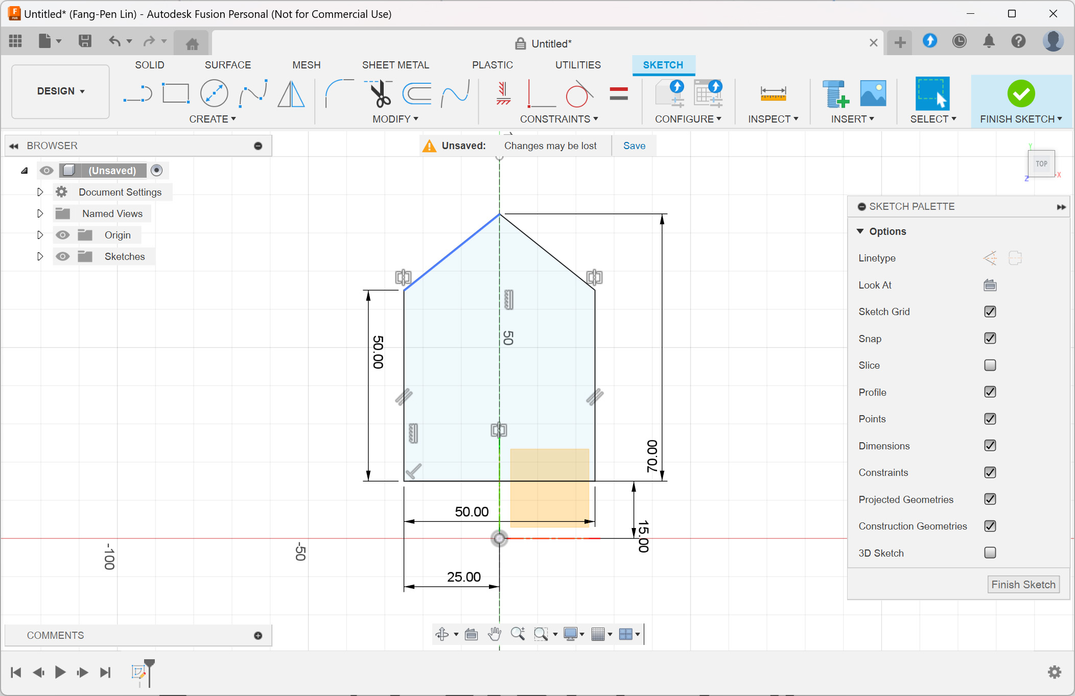
Screenshot of Fusion 360 showing constraints
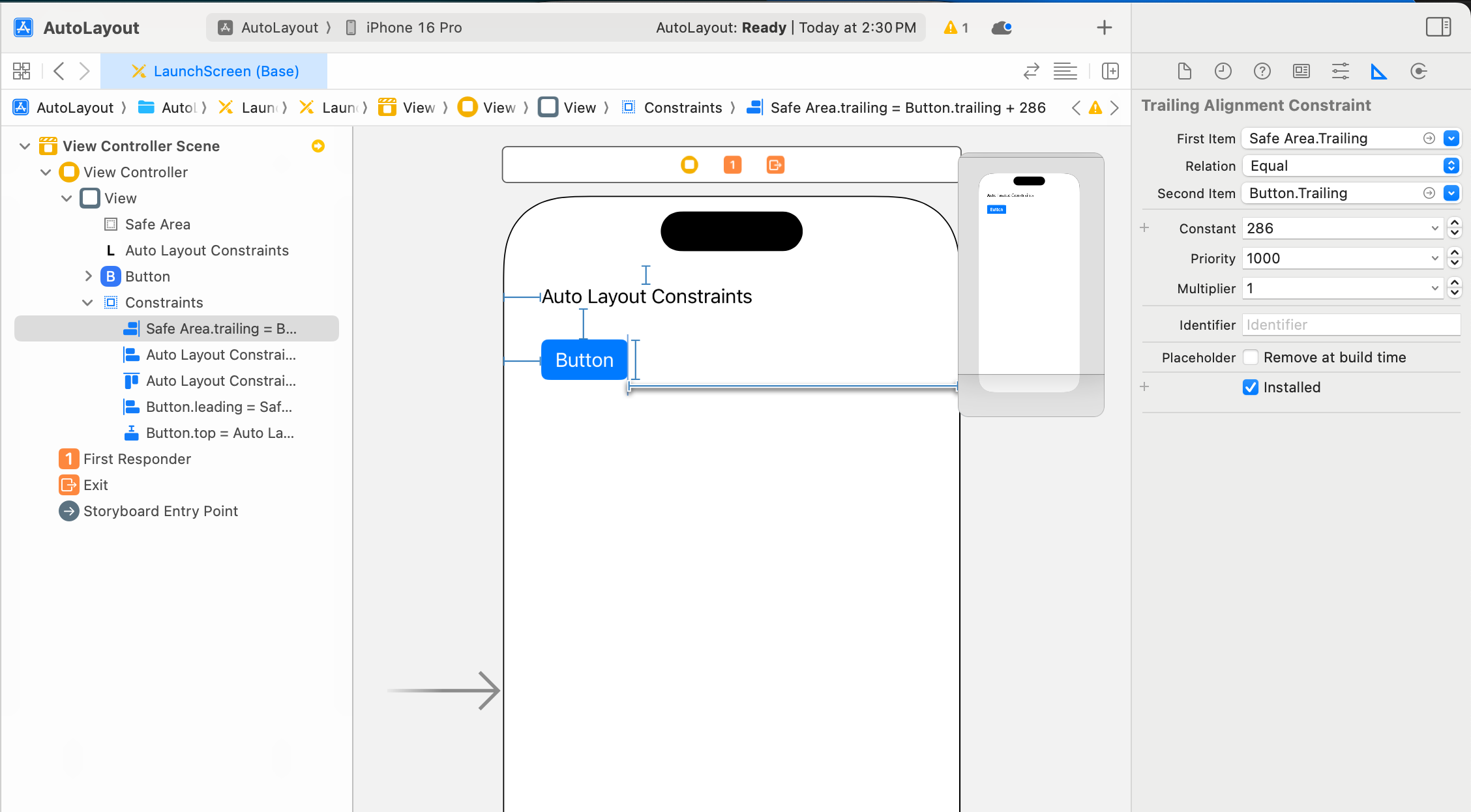
Screenshot of Xcode showing UI constraints
There’s the concept of constraints in CAD, just like the iOS UI auto layout system. The best practice is even the same: tutorials always suggest you define your constraints to make your sketch lines all well-defined, just like if you don’t have your UI constraints defined correctly, the layout could be broken in some situations. Since they are so similar, I’m curious if the iOS UI constraint concept is inspired by CAD, given that Apple is strong in industry design.
Parametric CAD is basically functional programming.
Another interesting feature I’ve learned in Fusion 360 is the timeline at the bottom left corner looks like this:
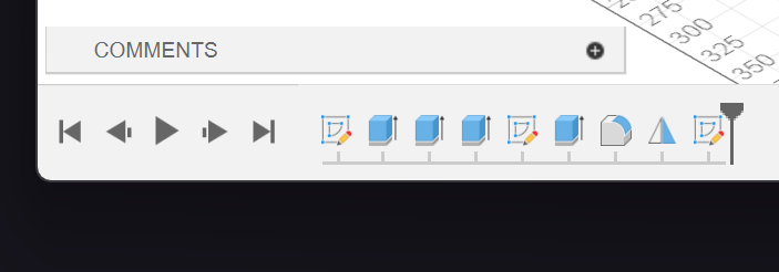
Screenshot of Fusion 360 Timeline (Steps) UI
It allows you to transform your previous sketch or model into another step by step. You can also move a specific step around, drop it, or go back and modify it freely. When I saw this, I said to myself:
Wait a minute, isn’t it just….
functional programming? 😲
Well, yes. If you compare this approach, there is no difference in how functional programming works. Instead of transforming simple numbers, strings, or data structures, you transform geometric objects with CAD in each procedure.

Comparing functional programming code to the Fusion 360 Timeline (Steps) UI
Later on, I realized it’s called Parametric CAD, and there’s another type of CAD called Direct Modeling CAD. For Fusion 360, it’s Parametric CAD. Since I am a big fan of functional programming and have written countless lines of functional code, it’s also a self-explanatory concept for me to pick up. The only new muscle I need to grow is to get familiar with what kind of geometric transformations are available and how to use them effectively.
Measurement and design
Now, the tool is ready; the only thing left is to take measurements and start the design phase. I bought an Electronic Digital Caliper and used it to measure the dimensions of the webcam, its mount, and the monitors. Since it’s the first iteration, I usually go with the easy and obvious design and then think about improvements later. I created a simple structure that can mount on top of the monitor and let the webcame ride on top of it. The result looks like this:
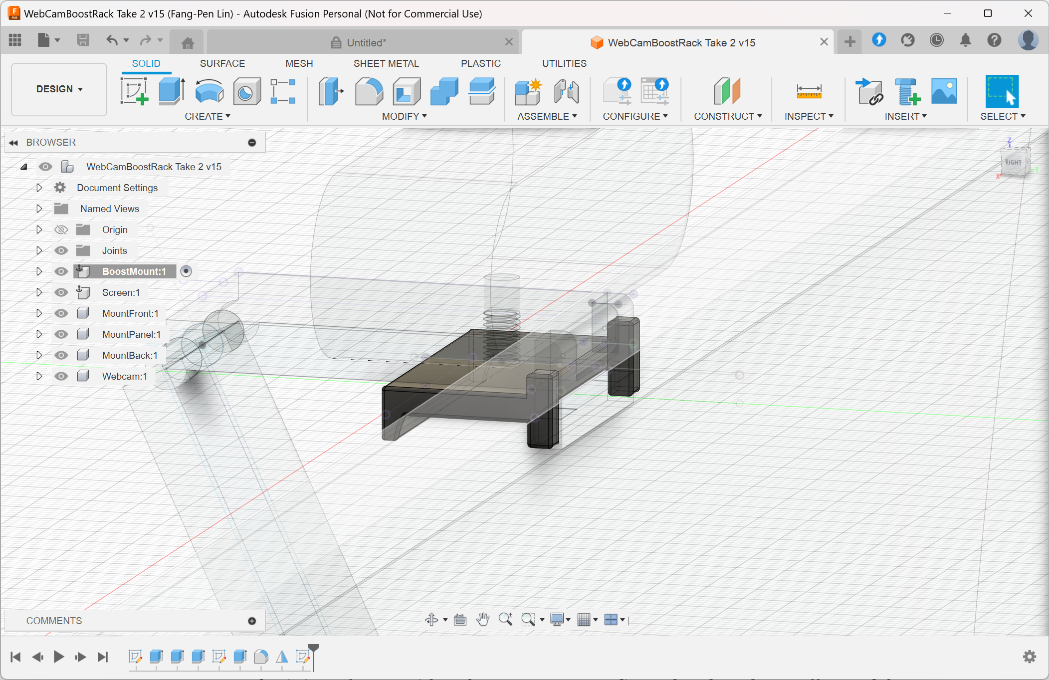
Fusion 360 screenshot showing webcam raiser model
At first, I only modeled the raiser itself, but later on, I realized I wanted to see how it looked in the virtual world; plus, it’s some good practice, so I also modeled the screen with the webcam altogether and let the raiser sit on top of it. That’s why you see them in my design.
Since I finished the design, I started poking around different features in Fusion 360, and I found the render mode. With that, I rendered a fancy product image and put some words on it.
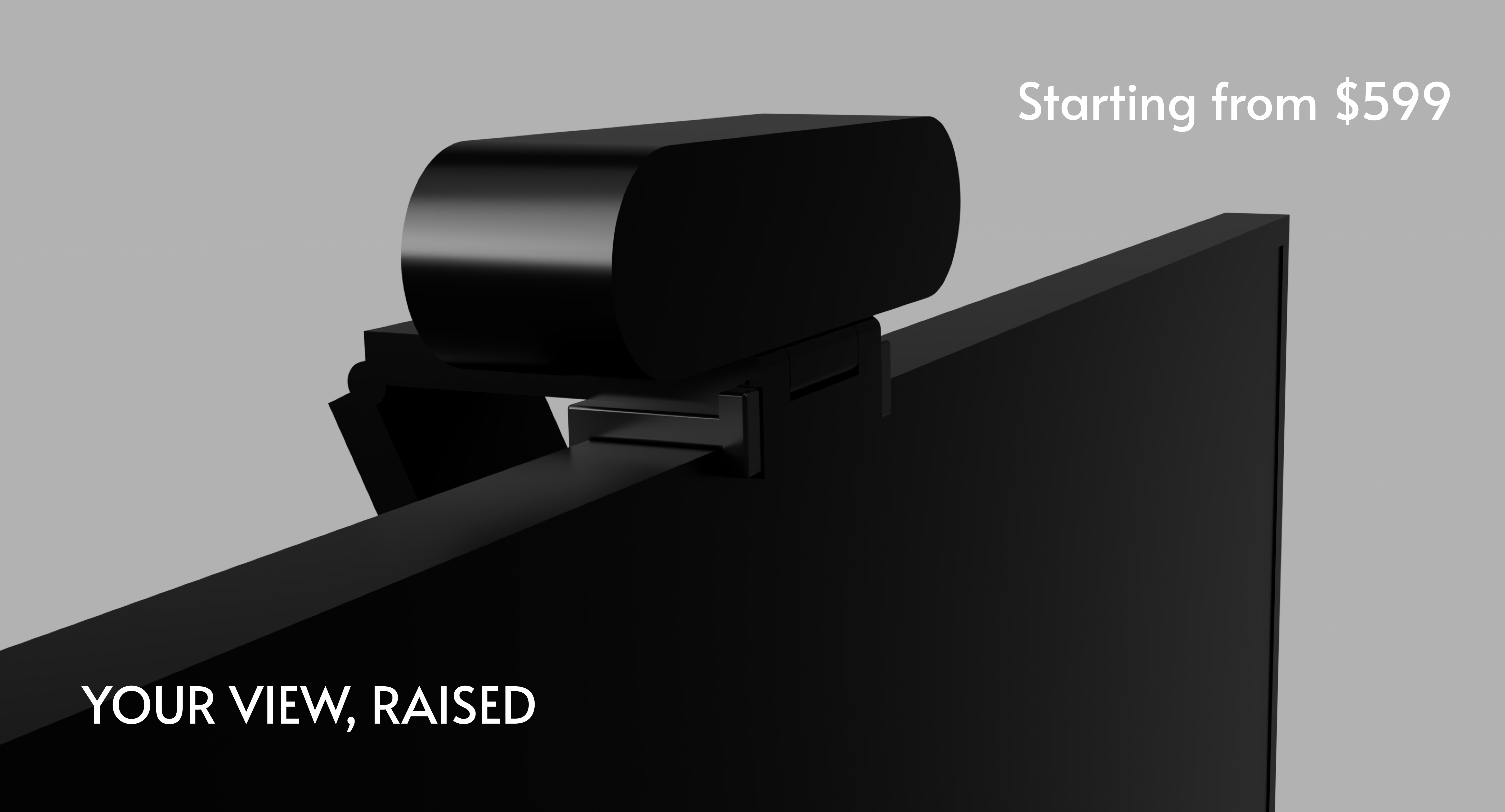
Webcam raiser model rendering result with text YOUR VIEW, RAISED and Starting from 599 text
Pretty cool, huh? Interested in buying my fancy 3D printed overengineered webcam raiser? Please let me know 🤑
Besides this obvious joke, my friend and I were considering selling the USB4-connected mini PC cluster with Kubernetes pre-configured and ready to roll out of the box. It might be useful if you want a local Kubernetes cluster for your local development or private applications. If you’re interested in it, please let me know by reaching out to me at [email protected]
That’s it for the part one. I still can’t find the time to print it. I don’t know if it fits, but I already had tons of fun learning CAD. While modeling was not hard for me, I soon realized that the hard part was to think about manufacturing, materials, and all other details in the design phase. Certainly, it may take a few iterations to learn from previous mistakes and improve in the long run. We may cover that later.
Finally, I hope you enjoy my experience sharing. See you next time in part 2!